
What I learnt:
- I didn’t know you can get inductors in the resistor package (L1, L2, L3)
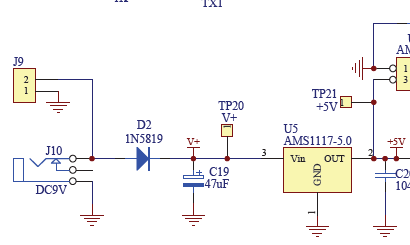
- The circuit is designed so that you can provide the power via the DC plug or a JST connector (see image below). They both are connected to a voltage regulator. I like that versatility.

There are also pads on the circuit which the instruction document tells you to bridge after you test the power supply which is very interesting
I’m not sure what the purpose is but here’s my guess. I believe once you confirm the power supply circuit is working you bridge those connections to interface the power supply of the circuit to the sensing side of the circuit and the microcontroller, ensuring you don’t damage them
I like the mounting and electrical connection of the TFT display. In addition to the main 32-way header pin connector, there are two 2-pin headers on the other side. This is for stability and mounting. NICE!
The MCU’s firmware can be reprogrammed using the UART pins that are broken out. See the image below. A USB-TTL module and performing the connections is required. This process is referred to as In System Programming (ISP)

Schematic
