Specs
- STC15W408AS MCU
- 4 buttons for volume and frequency control
- Current channel display via 4-digit 7-segment display
- Power via x2 AA batteries or micro-USB
- UART external programming available via broken-out RX, TX, VCC and GND pins
- External audio connector allowing connection to headphones or custom speaker

For being either the 1st or 2nd kit I assembled, I’m surprised it worked (after some rework).
After initial power-up, the 4 digit 7-segment display briefly powered up then shut off. I wasn’t 100% confident with the soldering for the 10-pin daughter PCB. I was certain the contacts of the PCB wasn’t actually connecting with the solder pad. There was a slight elevation. I removed the additional solder with solder braid then resoldered the connections.
Additionally I added more solder to the V- and F+ as they lacked solder on the top plane of the PCB.
After these changes, the circuit WORKED!
The soldering was a challenge, with a 16 pin SOIC SMD IC, a 10 pin daughter board with castellated pins, USB-C connector, 18 pin IC socket, battery holder and speaker. My soldering experience greatly improved.
The final product looks amazing. The transparent acrylic is amazing. I love how it allows you to see the bare electronics.
Schematic
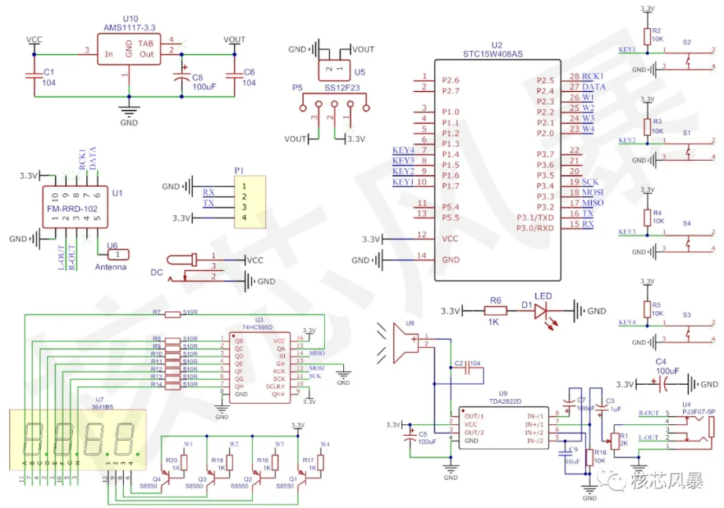
- A 74HC595 shift register controls the 4-digit 7-segment display
- AMS1117 for voltage regulation
- TDA2822D is a low-power audio amplifier, responsible for driving the speaker
- 10k pullups for button inputs.
Conclusion
This DIY kit sweetened my appetite for electronics and gave me a HUGE CONFIDENCE BOOST.