Introduction
Now we’re getting into the dangerous exciting stuff.
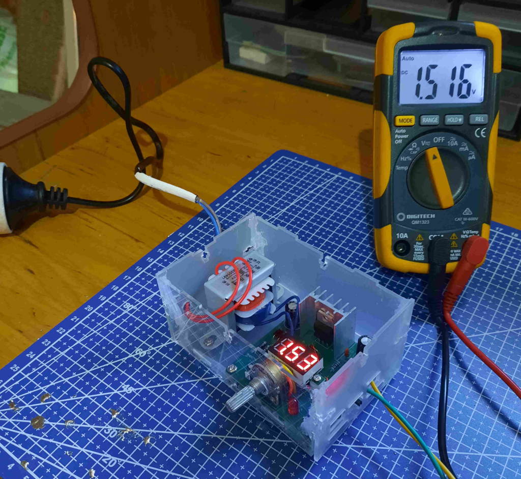
I recall this kit being fairly straightforward to assemble. No SMD components or fine-pitch THD component. Although I substituted the European AC plug with an Australian equivalent.
This is also the first project that runs off AC mains.
Schematic
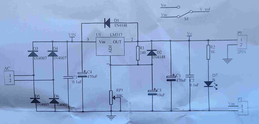
The schematic can be split into several sections:
- Step-down transformer (not shown in above schematic)
- Full-wave rectification
- LM317
Strangely, the 3 digit 7-segment display is not seen on the schematic. Also, the output of the step-down transformer is the 2-pin terminal block labelled AC
220V AC power is reduced to 12V AC by a transformer, rectified by diode D3-D6, filtered by capacitors C3 and C4, then sent to the LM317.
R1 and RP1 form the voltage regulation circuit. Changing the resistance of the potentiometer RPI changes the output voltage. What is very intriguing is that the output voltage is displayed on the 3-digit 7-segment display.
C1 and C2 are output filtering caps. D7 is an indicator LED. D7 is redundant due to the 3-digit 7-segment display
The heart of the circuit is the LM317 – a widely-used linear voltage regulator. It’s benefits include:
- Adjustable output voltage (1.2V – 37V)
- Output current >1.5A
- Wide voltage regulation
- Low noise
Conclusion
I really DIG the voltage output being displayed on the 3-digit 7-segment display.
Although, I’ve yet to test this PSU.