Background
Today, we’ll use a piezoelectric disk sensor and an EWMA-based algorithm to detect footsteps or other vibration events.
The Theory
The piezo’s output is read on the ADC, and the firmware runs exponentially-weighted moving averages to track the sensor’s resting bias (middleValue) and its noise envelope (highValue/lowValue). The difference between those, plus a pot-adjustable padding term, forms an adaptive deadzone — so the detector self-calibrates to ambient noise and the potentiometer sets sensitivity.
When a vibration (footstep, table bang) pushes the ADC reading past the deadzone thresholds, one of two LEDs lights depending on direction of the excursion, and a switch/relay output (PB7) is asserted. A countdown timer (ON_TIME / CYCLE_DELAY) holds the outputs on for a set duration after the last trigger, with each new trigger reloading it.
What is a piezo disk?
In essence, it is a sensor that allows you to generate electricity from movement.
A piezo disk is a crystal that when subjected to vibrations (say footsteps, taps on a tabletop) it produces a voltage. By sensing this voltage we can detect vibrations and use this to trigger stuff. This is the focus of this project.
It’s a special type of capacitor, the schematic symbol resembles a capacitor however it generates a voltage when deformed or squeezed.
Since piezo disks generate AC voltages, we’ll bias the piezo with Vcc/2 using a voltage divider, ensuring the Atmega328p can read it. Check Hardware connections heading for more information.
Exponentially Weighted Moving Averages (EMWA)
Imagine you have a sensor that is transmitting readings every second. If we take an average of 5 readings, we mitigate the effects of noise. However, you lose accuracy. However, if we increase this to 10, we can see the peaks however we need more memory.
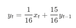
The EWMA used in this project only uses 2 values. The current value and previous value. The trick is that they do not have equal weights. In the code, we average 1/16th of the current value with 15/16ths of the average from the last period.
In our EWMA, we’ll average 1/16th of the current value and 15/16th of the historical value. Here’s how that looks like:
Hardware Connections
Schematic is available in the GitHub repository.
Ensure you weigh down the piezo with something large or you could sticky tape it to a surface.
The Software
This project consists of a single main.c.
We continuously measure the ADC pin connected to piezo. We calculate the middle value, high and low value. Then we determine if this exceeds the deadzone. If yes, we trigger stuff. If no, then the signal must be noise and we don’t do anything.
We track the moving average. In determining whether to trigger the LEDs, the threshold calculation compares the adc reading to the middle zone + deadzone. A footstep should be a large or small reading, thereby triggering on off the LEDs. This is how we detect a signal in an environment buried in electrical and mechanical noise.
The detection threshold is automatically adjusted to electrical or mechanical background noise.
FAQ
What are the LEDs supposed to do?
There’s a red one connected to PB7 and two green ones on PB0, PB1.
PB0 triggers for “negative” voltages whilst PB1 triggers for positive voltages.
What does PB7 do?
It’s called SWITCH in the code. It illuminates if a high or low value is detected.
How is the countdown implemented? How long do the LEDs stay on for after being triggered?
lightsOutTimer = ON_TIME / CYCLE_DELAY; gives you the number of loop increments or decrements of this variable. Multiply the result by CYCLE_DELAY to get the actual delay in seconds.
In the code it’s configured for 2000ms / 10ms = 2000ms.
The code begins decrementing this value. Once it reaches zero, TIME’S OUT. The LEDs shut off