Background
In 13. Taking DC Motors for a spin!, we implemented PWM speed control of a DC motor. However, this was limited to one direction. That’s not very useful. Let’s fix that by using a H-Bridge. We’ll design one ourselves using discrete components then use a dedicated H-Bridge IC, the L298N.
The Theory
A H-bridge allows us to spin a motor in the reverse direction. This project will implement a H-Bridge using 6 FET’s and 2 AVR I/O’s.
Additionally, it will use a commercial dual H-Bridge driver IC, the L298N configured for sign-magnitude PWM control. This allows us to control 2 DC motors with significantly less wires than manually wiring the H-Bridge.
1st Project – Manual H-Bridge
Hardware Connections
Before we use a dedicated H-Bridge IC, let’s construct it using discrete components. This is first-principles thinking and it allows us to appreciate a H-Bridge driver IC.
The schematic is available in the GitHub repository.
The high-side switches are P-Channel FETs. These conduct when $V_{GS}$ is negative. We can’t sink this through the AVR pin, thus we’ll use a N-Channel FET to sink it.
To avoid shoot-through, i.e. shorting the supply by conducting both high and low FET’s use the same/similar FET’s or add protection circuitry. This will be an optional exercise to bulletproof the circuit.
M5 switches M2, M6 switches M4.
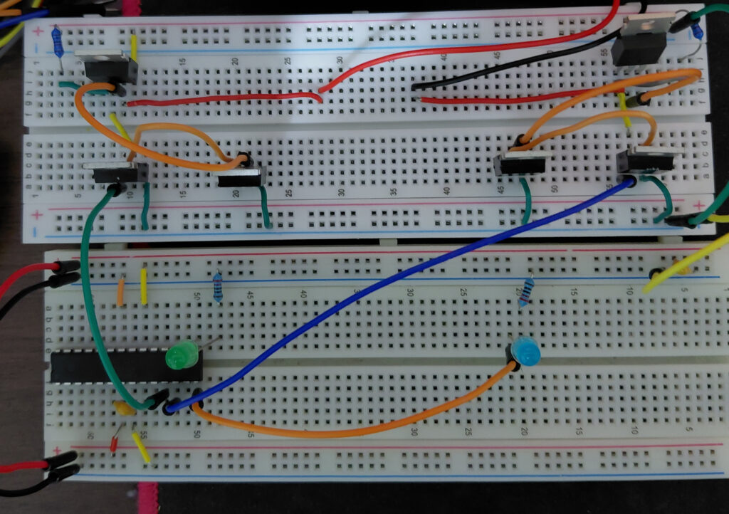
I chose to use 2 full-length breadboards as I was getting overwhelmed with the amount of connections.
The Software
The program consists of a single main.c.
The dc motor should move forward then brake. It should move backward and brake.
The motor should spin then rapidly stop. See lines 73 – 81.
Each “bridge” has it’s own indicator LED.
Showcase
2nd Project – The L298N
The circuit above works for one dc motor but what if you want to control 2 or 4 DC motors. Well, you’d have to double or quadruple the connections. This is not scalable.
This is where our friend, the L298N comes in. The is a dual-H-Bridge driver. One H-Bridge powers one DC motor.
OUT1, OUT2 is one H-Bridge. OUT3, OUT4 is the other. Connect one DC motor positive and negative wires to each OUT1, OUT2. Other DC motor to OUT3, OUT4.
This project is similar to schematic 1. We use 2 switches to control a H-Bridge except in this case we switch that is OFF is PWM’ed to provide speed control.
The code will implement sign-magnitude PWM control.
This is the possible combinations for a H-Bridge.
| Left input | Right input | Current path | Result |
|---|---|---|---|
| 0 | 0 | Motor shorted, low side | Braking |
| 0 | 1 | Right to left | “Forward” |
| 1 | 0 | Left to right | “Backward” |
| 1 | 1 | Motor shorted, high side | Braking |
For the pin that is LOW, rather than a solid 0, we’ll output a PWM signal, varying the speed. Thus, the list of choices looks like:
| Sign | Magnitude duty cycle | Result |
|---|---|---|
| 1 | 100% | “Forward” full speed ahead |
| 1 | 50% | “Forward” half speed |
| 1 | 0% | Dynamic braking |
| 0 | 0% | Dynamic braking |
| 0 | 50% | “Backward” half speed |
| 0 | 100% | “Backward” full speed |
Hardware Connections
I choose Fritzing to convey the hardware connections so I chose the L298N module.
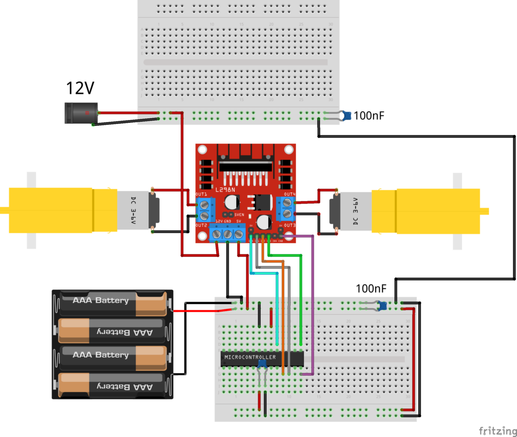
| L298N | ATmega328 |
|---|---|
| IN1 | PD6 (OC0A) |
| IN2 | PD5 (OCOB) |
| IN3 | PB1 (OC1A) |
| IN4 | PB2 (OC1B) |
| ENA | PB5 |
- ENB is not connected. One EN is shared between both bridges.
- IN1, IN2, IN3, IN4 are driven by PWM.
Software
The program consists of a L298N driver that is imported into main.c. Full source code available in the GitHub repository.
Timer 0 of the Atmega328p will control one motor and timer 1 the other motor. The 2 output compare match output OCnA of each timer will connect to each motor.
The driver uses sign-magnitude PWM control to adjustment of motor speed and direction.
This works like a normal H-Bridge with 2 low-side FET’s except the FET which is not conducting is being PWM’ed. This effect produces a variable speed.
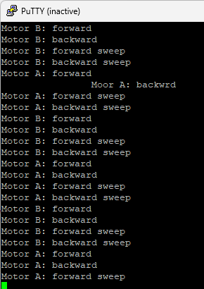
The code drives each motor forward, backward, then sweeps speed up and down in each direction, pausing at brake between direction changes.