Background
Stepper motors combine the precise accuracy of servo motors with the rotational movement of dc motors. Their the best of both worlds!
Their found in applications requiring high positional accuracy such as printers, scanners and robotic arms.
A stepper motor consists of two coils and depending on how we energize the coils we can manipulate the shaft to rotate and therefore point at a specific direction.
The Theory
Introduction to stepper motors
Stepper motors combine the precise accuracy of servo motors with the rotational movement of dc motors. Their the best of both worlds!
Their found in applications requiring high positional accuracy such as printers, scanners and robotic arms.
Their called stepper motors as every time the magnetic field reverses, the shaft rotates or steps a fixed number of degrees.
Unlike a normal DC motor which has a commutator, a stepper motor DOESN’T HAVE ONE! Rather we have to energize the coil windings in a specific sequence to rotate the shaft. Don’t be alarmed. This extra work comes with benefits
- We can control when the stepper takes a step
- We can control how many steps it’s taken or should take
- We know current angle of the shaft after rotation
A stepper motor has 2 windings, thus, 2 H-Bridges are required. Rather than explode the BOM count, we’ll use the SN745510, a dual H-Bridge driver IC. However, this is basic. You can use dedicated stepper motor IC’s.
Kinds of stepper motors
Stepper motors come in various flavours however the one we’ll focus on is a hybrid stepper with 200 steps per revolution driven in bipolar mode.
This is 50 steps per quadrant! This is alot of resolution.
Bipolar mode means we drive the stepper by energizing one coil after another. We toggle the left and right side of the H-Bridge, thus the term bipolar. This refers to the 2 halves of the H-Bridge.
Full stepping and half-stepping
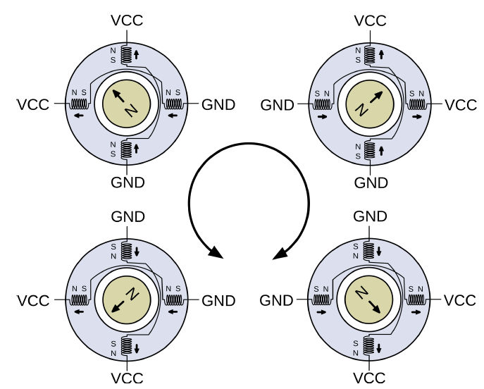
In full-stepping, both coil windings are energized. This emits a magnetic field which repels the magnetic field of the electromagnet. This causes a deflection/rotation of the shaft/rotor.
To perform a step, we reverse the polarity of one winding, due to magnetic fields the shaft will rotate.
In the image below, the windings are energized in a specific sequence that causes the shaft to spin clockwise. In our code, we’ll be implementing this sequence.
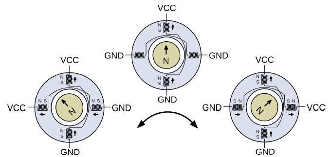
In full-stepping for each stage in the sequence, we reversed the polarity of one winding. In half-stepping, we won’t do this but rather GND it, then reverse the polarity. This gives us greater resolution, 400 rather than 200. It looks like this. Notice, the shaft can rotate true N now.
Microstepping
In half and full stepping we energize the coil either with VCC or GND. However, if we energize it with a PWM signal, thereby giving the coil a % of VCC, then we gain significantly more resolution than half-stepping. However, significant math is required according to the author. This project won’t implement microstepping but leaves it as an extension. You can purchase dedicated microstepping IC’s such as Allegro A4988 or TI DRV8825.
Identification of stepper motor wires
Since a stepper motor consists of 2 windings, the minimum number of wires is 4. 2 coils with both ends exposed/available for connection. However, their are 6 and 8 wire steppers. It all depends.
What we need to do is pair with the wires with one coil. Use an ohmmeter to determine the two ends of one coil.
The SN754410
This is a 4 half-H-Bridge driver IC. One H-Bridge controls one coil, connected to either end. Thus, this IC allows us to control a stepper motor with one IC, since 4 half-H-Bridges is equivalent to 2 full-H-Bridges. One H-Bridge per coil.
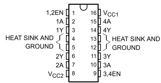
1 OUT/1Y, 2 OUT/2Y represent the 2 halves of a single H-Bridge. This is where we connect the 2 ends of a coil. “Y” represents a driver output.
1 IN/1A, 2 IN2/A are the control/input signals. We connect this to the Atmega328p.
Pin 8 is VCC for the motors. A dedicated supply ensures we don’t brownout the Atmega328p if the stepper draws alot of current.
Project 1 – Using the SN754410
NOTE: For the videos, I fitted a 6-spoke wheel on the shaft of the stepper. This allows me to more clearly see the positional accuracy of the stepper and its movements.
Hardware Connections
The schematic is available in the GitHub repository.
We’ll have the signals that control each side of a H-Bridge to the x IN pins.
The only inconvenience is that the schematic symbol doesn’t align with the horseshoe-shaped pinout of the IC.
The Software
This project will have two programs to test out.
1. Partial Stepper Showcase
In the main.c, the following occurs:
- The stepper will rotate forward 180 degrees or 200 steps.
- After 3 seconds, it will rotate backward for 360 degrees.
- After 3 seconds, it will rotate forward for 25 steps
- After 3 seconds, it rotates backward for 50 steps
Showcase
You can clearly see the positional accuracy of the stepper
2. Advanced Stepper Showcase
The program controls the stepper to perform the following movements with a delay between each:
- 2 forward revolutions
- half backward rotation
- A quarter forward rotation
- A backward eighth rotation
- A backward quarter rotation
- A forward eighth rotation
- A half forward rotation
This program includes the function trapezoid_move();
In partial_stepper_workout.c, the program moves the stepper from 0 → full speed then halts in abruptly. If the delay is minimal and speed is great, due to inertia of the rotor, this can result in missed steps. Also, it results in jerky, start-stop movements which is unprofessional. Let’s be professional.
This program adds the function trapezoid_move() to implement acceleration control. It consists of 3 stages. A ramp up, cruising, ramp down. You can simply add this function into partial_stepper_workout.c. We do this by removing delay argument and implementing it as part of the function. We don’t trust the user.
The steps that are used in ramping up or down is subtracted from the total step count, how_many_steps.
The ramp up/down profile is identical if stepper is rotating forward or backward.
The way the de-acceleration is implemented is so simple but it works. On each step, we simply add to the delay variable until we’ve reached the step count, steps_taken >= how_many_steps.