Background
A crash course on using an LCD will be demonstrated.
The Theory
An LCD is a type of display technology
Displays are components used to communicate information to the user. They can be as simple as LEDs and 7-segment displays or as advanced as OLED’s.
An LCD conveys information in a 2D grid of rows and columns. Each “cell” is composed of tiny liquid crystals (hence the name LCD) arranged in a grid and can display letters, numbers and sprites. However, the graphics it can render is extremely simple.
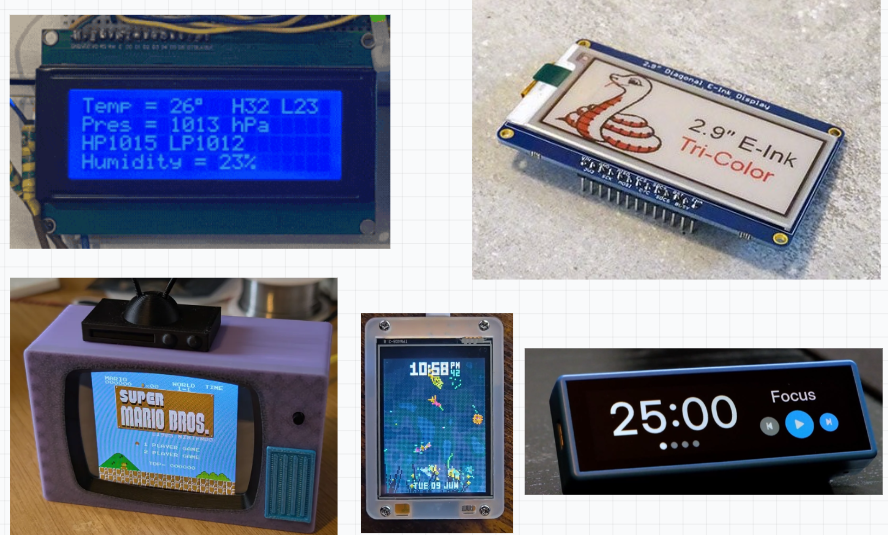
There are other display technologies such as OLED, TFT and e-paper displays. All of them vary according to: price, power consumption, interface, driver support, graphics and colour. A comparison of display technologies is tabulated below.
| Attribute | Character LCD (16×2, HD44780) | OLED (0.96″ SSD1306) | TFT (2.4–2.8″ ILI9341) | E-Paper (1.54″ e-ink) |
|---|---|---|---|---|
| Typical price | ~$2–5 | ~$3–8 | ~$8–15 | ~$15–30 |
| Power draw | ~40 mA logic + ~30 mA backlight | ~10–20 mA (no backlight) | ~60–80 mA (backlight heavy) | µA-level idle; power only on refresh |
| Interface | I2C (via backpack) or parallel | I2C or SPI | SPI (or parallel) | SPI only |
| Driver / libraries | HD44780 · LiquidCrystal (ubiquitous) | SSD1306 · Adafruit / U8g2 (excellent) | ILI9341 · Adafruit GFX / TFT_eSPI (well supported) | GxEPD2 / Waveshare (fiddlier, needs waveform tables) |
| Graphics & resolution | Text only, 16×2 characters | 128×64 monochrome graphics | 240×320, rich full graphics | 200×200+, high res but very slow refresh |
| Color | Monochrome (fixed backlight) | Monochrome (or yellow/blue) | Full color (65K) | B/W (some 2–3 colour), slow |
For every-day usage, OLED’s are a strong choice. They deliver 128×64 graphics at a small power draw at a competitive price to an LCD. For a richer, more immersive display, the TFT would be apt at the cost of a higher power consumption and price.
A TFT display would be suitable for a video game console as it delivers rich and immersive graphics. They come in various resolutions. For a smartwatch, an OLED provides high-contrast animated graphics in a compact size. An e-paper display thrives in a deployed weather station where it must run for weeks on a battery.
Technical Summary
The display I’ve selected is a Vishay LCD-016N002B-CFH-ET LCD module driven by an ST7066 controller. It has 2 rows and 16 columns. This is a Character 16×2 LCD. This means it can display characters. We communicate with the LCD the same way we do with sensors and microcontrollers, by writing and reading to certain registers.
There are LCD’s that are operated via I2C, however the one I selected communicates via a 8-bit data bus. If I were to redo this project, I’d chose the I2C-operated LCD to save I/O’s.
This LCD has a 1/16 duty cycle. The LCD has 2 rows and each cell has 8 rows. Thus, when rendering graphics, the controller must scan 16 rows total. 1/16 means that each row is energized for 1/16th of the time. Each row is one for 1/16’th of a frame and off for 15/16. However, due to the refresh rate (typically 60-100Hz) it appears as if each row is illuminated.
This explains why the contrast varies. Each pixel is receiving a portion of the driving voltage according to the duty cycle. Luckily, the contrast pin (V0) allows us to adjust the contrast.
This LCD has 2 rows and 16 columns. Thus, it can render 32 “icons”. Let’s call each possible position a cell. A cell is comprised of 5×8 dots. Each dot-size is 0.55mm x 0.65mm. The total cell dimension is 2.95mm x 5.55mm. (row x col). Any characters we draw is limited to 2.95mm x 5.55mm. This will be relevant for drawing custom graphics via CGRAM.
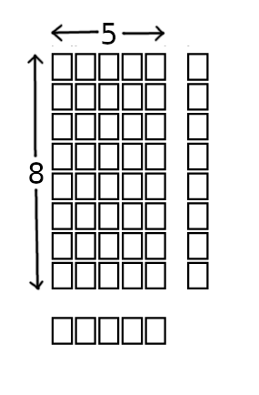
The image below gives you an idea of each cell when the LCD is viewed as a complete module.
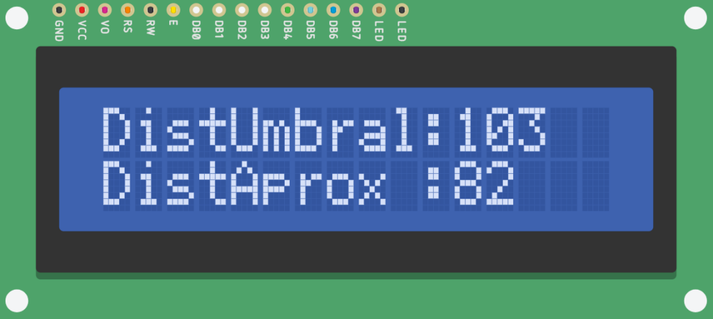
To write a graphic to a cell, we must communicate with it’s address. This involves writing to a character code to DDRAM. This maps to a glyph. The controller then renders the bitmap. The contents of DDRAM is shown below.

The LCD’s view direction is optimized for 6 o’clock. This is the most optimal viewing angle/direction. It has to do with how the liquid crystals are polarized … or something. Just don’t look at it with a birds-eye view or from the side.
Functional Description
The LCD has two 8-bit registers, an Instruction Register (IR) and a Data Register (DR). The RS pin is used to select either one of these registers. Afterwards, the R/W pin is used to either read/write from the selected register.
The IR register contains the full instruction set of the LCD such as clear LCD, move cursor and shift display left and set CGRAM address. It can only be written to.
The DR register is a buffer that stores characters written or read from Display Data RAM (DDRAM) or Character Generator RAM (CGRAM).
Display Data RAM (DDRAM)
The display data is stored as 8-bit character codes. Its extended capacity is 80×8 bits or 80 characters.
Character Generator ROM (CGROM)
The LCD controller has 200 presets called glyphs which are stored in its ROM. You simply transmit the 8-bit character code and the controller looks up the bitmap and drives the segments.
CGROM can generate icons from a 5×8 dot or 5×10 character patterns derived from a 8-bit character code.
The datasheet contains a table which is essentially a 16×16 lookup table of all the built-in glyphs. The 8-bit character code we write to DDRAM is split. The upper nibble is on the columns, lower nibble along the rows.
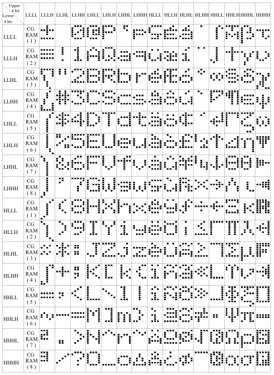
Character Generator Ram (CGRAM)
This is how the user can render custom graphics, e.g. a cherry icon or battery symbol. There are two modes: Firstly, 5×8 dots, allows you to write 8 character patterns. On the other hand, 5×10 dots, allows you to write 4 character patterns. The character pattern is the actual bitmap, a nxm representation of which dots are illuminated.
LCD Pinout
The LCD I’m using has 14 pins.
My module from AliExpress has 2 extra pins, pins 15 and 16.
The LCD has 2 registers: Command and data register. We select the register by outputting a voltage on RS. 1 = data register. 0 = command register.
| Pin | Name | Description |
|---|---|---|
| 1 | VSS | GND |
| 2 | VCC | 5V |
| 3 | VEE | Power supply to control contrast |
| 4 | RS | 0 = Select command register. 1 = Select data register |
| 5 | R/W | 0 = Write. 1 = Read |
| 6 | EN | Enable |
| 7 | DB0 | 8-bit data bus |
| 8 | DB1 | 8-bit data bus |
| 9 | DB2 | 8-bit data bus |
| 10 | DB3 | 8-bit data bus |
| 11 | DB4 | 8-bit data bus |
| 12 | DB5 | 8-bit data bus |
| 13 | DB6 | 8-bit data bus |
| 14 | DB7 | 8-bit data bus |
| 15 | BLA | Backlight Anode. Connect to 5V |
| 16 | BLK | Backlight Cathode. Connect to GND |
R/W allows us to read/write to the LCD. 1 = Read. = 0 Write
D0-D7 is the 8-bit data bus. To send characters, we do RS = 1, send the 8-bit ASCII equivalent of the character/letter/symbol we want displayed. Below are the list of possible instructions we can transmit to the LCD. Think of it as the Instruction Set (ISA).
| Code (Hex) | Command to LCD Instruction Register |
|---|---|
| 1 | Clear display screen |
| 2 | Return home |
| 4 | Decrement cursor (shift cursor to left) |
| 6 | Increment cursor (shift cursor to right) |
| 5 | Shift display right |
| 7 | Shift display left |
| 8 | Display off, cursor off |
| A | Display off, cursor on |
| C | Display on, cursor off |
| E | Display on, cursor blinking |
| F | Display on, cursor blinking |
| 10 | Shift cursor position to left |
| 14 | Shift cursor position to right |
| 18 | Shift the entire display to the left |
| 1C | Shift the entire display to the right |
| 80 | Force cursor to beginning of 1st line |
| C0 | Force cursor to beginning of 2nd line |
| 28 | 2 lines and 5 × 7 matrix (D4–D7, 4-bit) |
| 38 | 2 lines and 5 × 7 matrix (D0–D7, 8-bit) |
Table 2: LCD Command Codes
Project 1 – Hello World
Let’s get up and running with the LCD.
Hardware Connections
The schematic is available in my GitHub repository.
Highlights:
- Data bus on Port D
- Command port on PC0 – PC2
- Backlight adjustment via R1
The Software
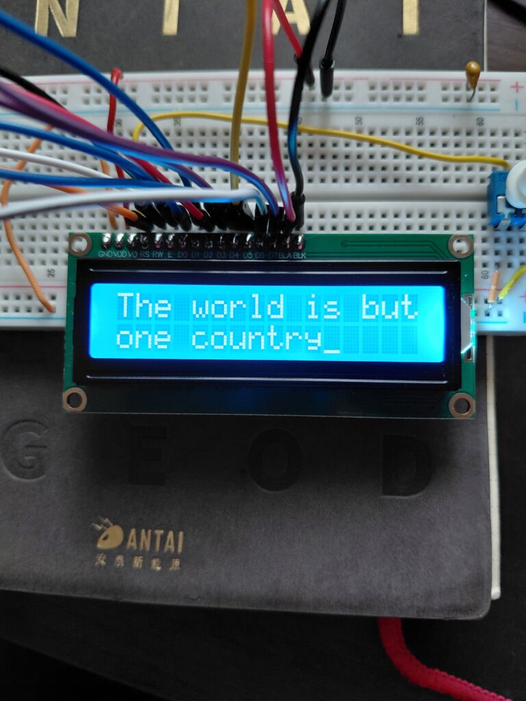
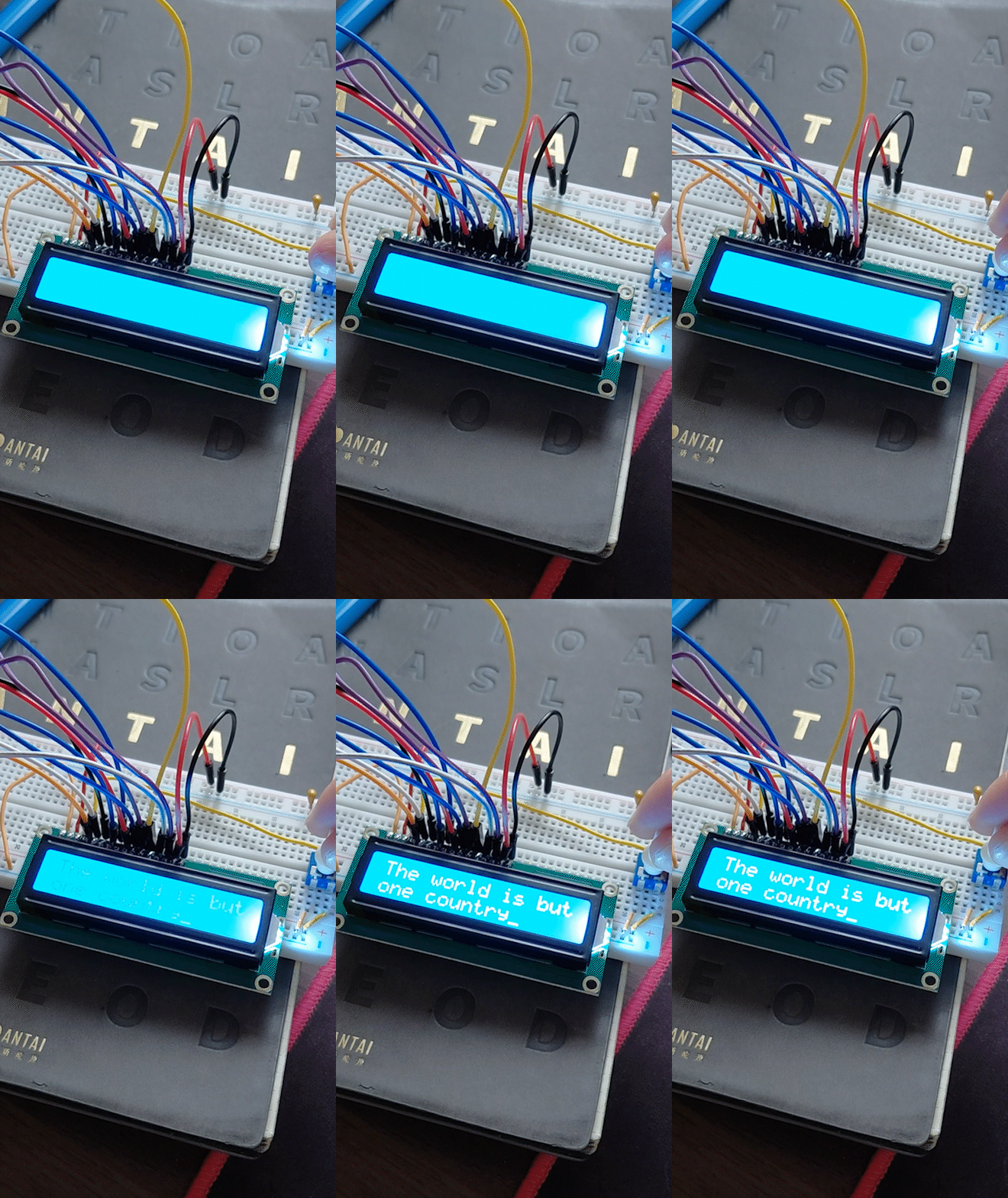
The program consists of a single main.c and its corresponding Makefile. The program initializes the LCD and prints a message, The world is but one country.
The Makefile saves us the headache of compiling the project. This includes dependencies and files from other file paths. Also, it contains project configuration settings.
Firstly, the LCD is initialized via you guessed it lcd_init(). Numerous steps are involved during initialization. Firstly, we sett the data bus and command port HIGH. We configure it for 8-bit mode, turn on the display, turn on the cursor and shift it to the right. These instructions reach the LCD through lcdCommand(), which accepts specific hex codes for each operation — see Table 2: LCD Command Codes. The cursor is then positioned at (1,1), the upper left, and the message is printed.
To print a message, the firmware invokes lcdprint(). This function invokes lcdData() for each character. This function implements the write cycle as conveyed by the datasheet. It is reproduced below. lcdData() implements these steps in code however with one deviation. Data is placed on the bus, before the setup window. It is assumed that the bus is stable.
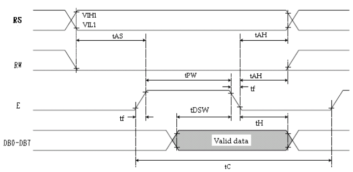
- Send data (single
char) on data bus - Select data register by setting
RS = 1 - Write to the register by pulling
RWlow - Pull
ENhigh - Wait one second before clearing
EN
Full program available in my GitHub repository.
Project 2 – 4-Bit Mode
We learnt about and flashed a Hello World program to the LCD. Fantastic!
Although, if you examine the schematic, you’ll notice that the data bus is 8-bits long. In some applications, you might not have the luxury of that many I/O’s. Luckily, the LCD has a 4-bit mode. This cuts the number of connections from 8 to 4.
NOTE: There is a version of this LCD that is I2C-compatible. Thus, further reducing the amount of connections.
Hardware Connections
The schematic is available in my GitHub repository.
Highlights
- Command port on PB0-PB2
- Data bus connected to high nibble of PORTD (PD4-PD7)
The Software
The program will initializes LCD and prints a message. It’s very similar to Project 1 apart from a few differences.
In lcd_init() we transmit the hex commands to initialize LCD to 4-bit mode. When transmitting data, in order to transmit 8 bits of information into 4 bits we perform a mask and bit-shift by 4 places. This behaviour is seen in lcdData(), lcdCommand().
As always, full program located in my GitHub repository.
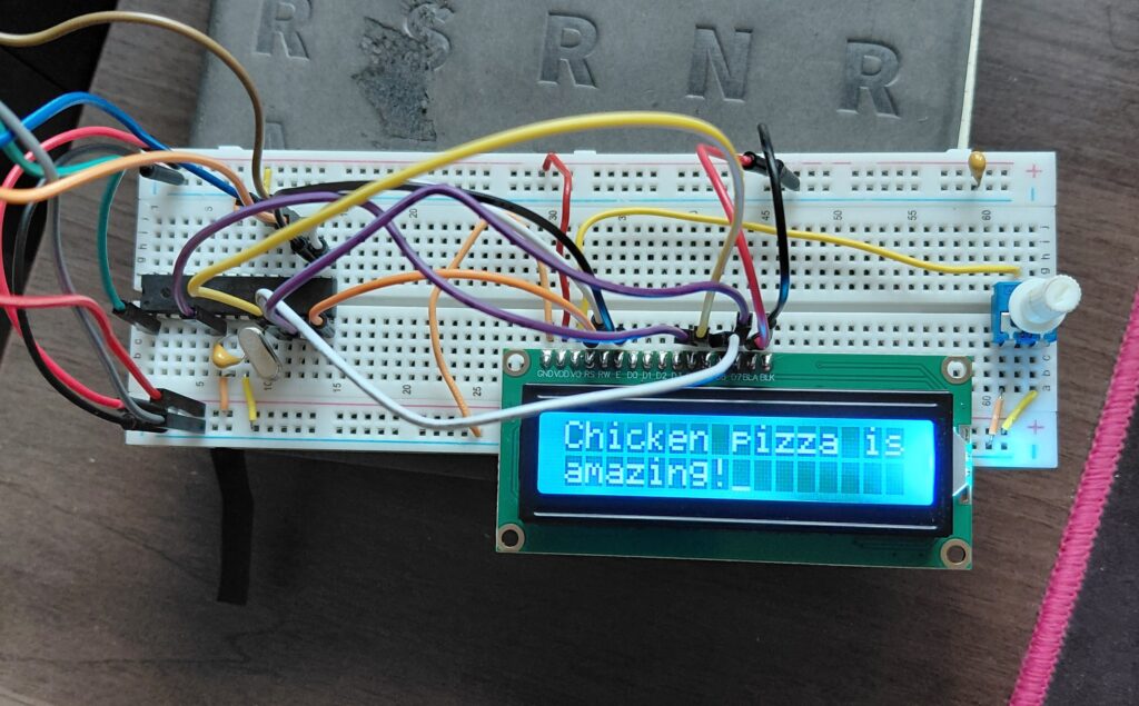
Project 3 – Scrolling Text via UART
We’ve printed a simple message to the LCD. It’s time to step things up a notch! This program accepts a string via UART and prints it on LCD as scrolling text. Pot on PC0 adjusts scroll speed.
Hardware Connections
Nothing to see here. Identical to Project 2, except a potentiometer is connected to PC0. This is to adjust the scroll speed.
The schematic is available in my GitHub repository.
The Software
Two libraries are used: lcd_driver, USART.
Since this is a longer program than Project 1 and 2, it makes sense to compartmental LCD functions into a separate driver.
main.c
Macros are defined for scroll-speed and the display.
The scroll speed is connected to PC0, an ADC pin. We initialize the ADC by configuring the multiplexer, clock prescaler and disabling the input buffer. We read the ADC with a polling routine via adc_read().
Performs initialization of ADC, UART, LCD. LCD prompts user for text, confirms it’s not nonzero then scroll_display() is invoked. After it finishes, LCD clears and is ready for new text to scroll.
Reading the potentiometer — pot_delay_ms()
pot_delay_ms() is called for each time we “scroll” the display. Let’s call this a frame. It’s the implementation of the Arduino-equivalent map() except it doesn’t cost 200 cycles but rather 42. A higher voltage maps to a shorter delay. At this setting, you’ll visibly notice the individual frames scrolling by.
static uint16_t pot_delay_ms(void)
{
    uint16_t adc   = adc_read(0U);
    uint16_t range = (uint16_t)(SCROLL_MS_MAX - SCROLL_MS_MIN);
    /* invert: adc=0 → max delay, adc=1023 → min delay */
    return (uint16_t)(SCROLL_MS_MAX - ((uint32_t)adc * range >> 10U));
}
| Pot position | ADC | delay | speed | time to cross all 16 columns |
|---|---|---|---|---|
| fully CCW | 0 | 600 ms | 1.7 chars/s | 9.6 s |
| centre | ~512 | 325 ms | 3.1 chars/s | 5.2 s |
| fully CW | 1023 | 51 ms | ~20 chars/s | 0.8 s |
Scrolling the display — scroll_display()
Let’s move our attention to the main workhorse of this program, scroll_display()
For scroll_display(), we render a frame that loops according to the length of the message (the argument) and a padding, the number of LCD columns (LCD_COLS). We loop through LCD_COLS and transmit a char at a time. We add a delay according to pot_delay_ms() between frames.
A frame is a redrawing of row 1. This is the inner loop with LCD_COLS as loop variable.
static void scroll_display(const char *msg)
{
    uint8_t len   = (uint8_t)strlen(msg);
    uint8_t total = len + (uint8_t)LCD_COLS;
    uint8_t step, col;

    for (step = 0U; step < total; step++)
    {
        uint16_t delay = pot_delay_ms();   /* sample pot before each step */

        Lcd_SetCursor(0U, 0U);
        for (col = 0U; col < (uint8_t)LCD_COLS; col++)
        {
            uint8_t src    = col + step;
            uint8_t offset = (uint8_t)(LCD_COLS - 1U);
            char    ch;

            if (src < offset)
                ch = ' ';
            else if ((src - offset) < len)
                ch = msg[src - offset];
            else
                ch = ' ';

            Lcd_WriteChar((uint8_t)ch);
        }

        delay_ms_var(delay);
    }
}
readString()
The main function from the USART library is readString(). The others are printString(), initUSART())
Anyways, readString() captures the user’s input. It works by appending a char of arrays according to the length of the user’s submitted sentence. This function simply delegates work to receiveByte(), transmitByte(). Very cool how the advanced functions are built from simpler ones.
void readString(char myString[], uint8_t maxLength) {
  char response;
  uint8_t i;
  i = 0;
  while (i < (maxLength - 1)) {                   /* prevent over-runs */
    response = receiveByte();
    transmitByte(response);                                    /* echo */
    if (response == '\r') {                     /* enter marks the end */
      break;
    }
    else {
      myString[i] = response;                       /* add in a letter */
      i++;
    }
  }
  myString[i] = 0;                          /* terminal NULL character */
}
Full source code located in my GitHub repository.
Verification
- After flashing, open a serial terminal at 9600 8N1 at the AVR’s COM port.
- Serial terminal should display:
Enter text: - Type
The world is not round, but flat!and press Enter. The text should scroll right-to-left once across row 0 while row 1 shows << scrolling >>. - After the scroll finishes the LCD goes blank and serial terminal displays
Enter text:on a newline.
The Showcase
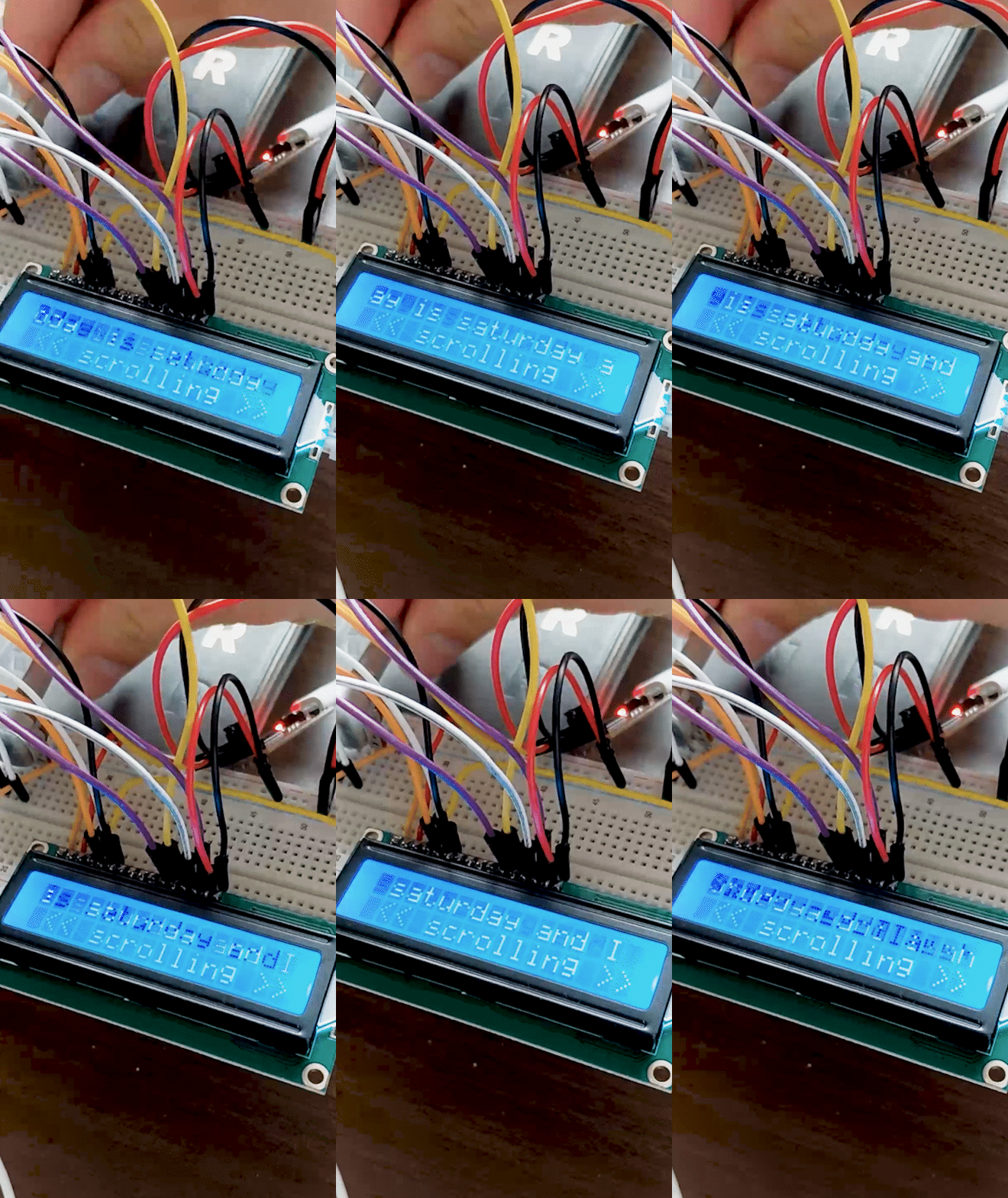
Video below demonstrates adjusting the scroll speed.