Background
The MAX7221 IC is a 4-digit 7-segment display driver. If you read 27. Ember – A Pomodoro Desk-Lamp Controller, you’d remember that we used a single 4-digit 7-segment display. This requires 12 connections! The 8 segments (A, B, C, D, E, F, G, DP) and 4 digits (DIG1, DIG2, DIG3, DIG4). If you’d like more digits, perhaps if you’re doing a scoreboard then the connections begins to get overwhelming.
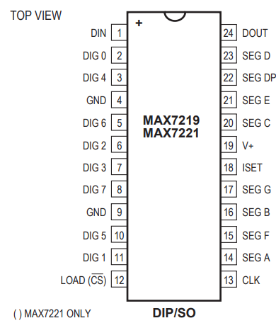
This is where the MAX7221 IC can greatly assist us. Take a look at the pinout. Rather than tie up 12 I/O’s from the MCU, we connect to the MAX7221 IC. It communicates via SPI.
The MAX7219 has three modes worth showing off:
- Code-B decode (hardware BCD→7seg for numbers)
- No-decode raw mode (you send segment bitmaps → arbitrary letters/animations)
- Intensity register (16-level PWM brightness)
For this project, we’ll focus on option 1.
Project 1 – Stopwatch
This is self-explanatory.
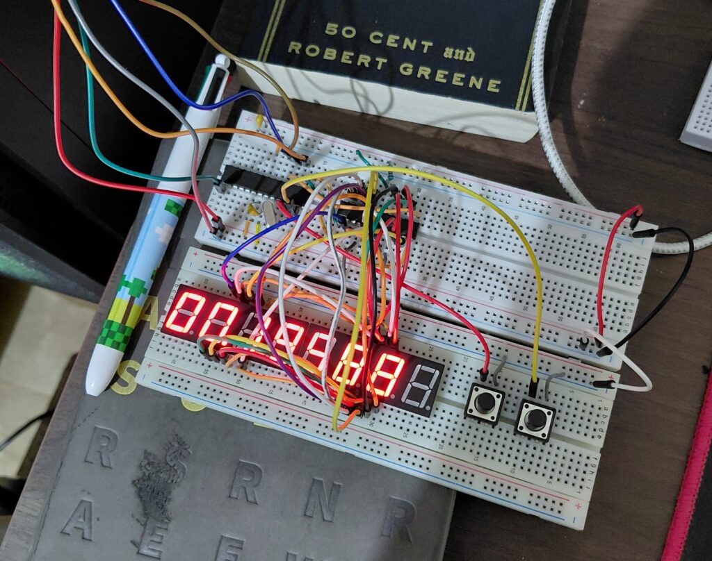
2 buttons serve as the UI. One of them starts and stops the stopwatch. The other clears it to zero.
DIG 0 – DIG1 = Minute
DIG2 – DIG3 = Seconds
DIG4 – DIG6 = Milliseconds
3 digits are allocated to counting the milliseconds as I wanted to convey the urgency of time lapsing.
Hardware Connections
I’m daisy chaining two common-cathode 4-digit 7-segment displays. This entails connecting the segment pins of both displays together and the 8 DIG pins to the MAX7221 IC. We sink the segments of each DIGx into the MAX7221 IC.
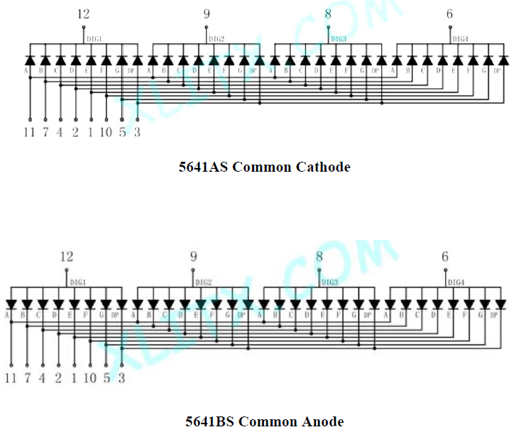
The schematic is available at my GitHub repository.
The Software
Full source code is located in my GitHub repository.