- Background
- What is Digital Dash?
- Hardware Connections
- The Software
- Project Structure
- Build System
- hardware_connections.h
- sys_tick.h/.c – The Game’s “Heartbeat”
- What is cooperative scheduling?
- buttons.h/.c
- How do we know which button was pressed if an interrupt on a group of pins trigger the same ISR?
- buzzer.h/.c
- sprites.h/.c
- rng.h/.c
- rng_rang() uses % operator to constrain the PRNG. How?
- high_score.h/.c
- game.c/.h
- main.c
- The firmware uses utility functions from the standard library
- Showcase
- FAQ
- Describe the death sound that plays
- This program is a side-scrolling endless runner. Describe the RNG of the program? How are the obstacles generated? Are they stored in an array?
- What’s the difference between TICKSPEED and s_ms. Both are related to game-timing
- I don’t understand what occurs in PCINT_vect.
- How does the same ISR, PCINT_vect service 2 I/O’s?
- loop_breaker tracks whether we’ve hit a collision. However, what I don’t understand is how does it cause a game over event. game_end() begins with executing the death sound.
- How complex is the scoring system? Does the score increase as game time increases? Do certain obstacles award more score?
- How is the high score tracked?
- A floating ADC pin is used for RNG engine. Can Mersenne Twister be used. How much memory does the library occupy? I’m actually curious.
Background
Previously I covered LCD’s in extensive detail in 20. Intro to LCD. Let’s do something useful with it. How about programming a simple game.
What is Digital Dash?
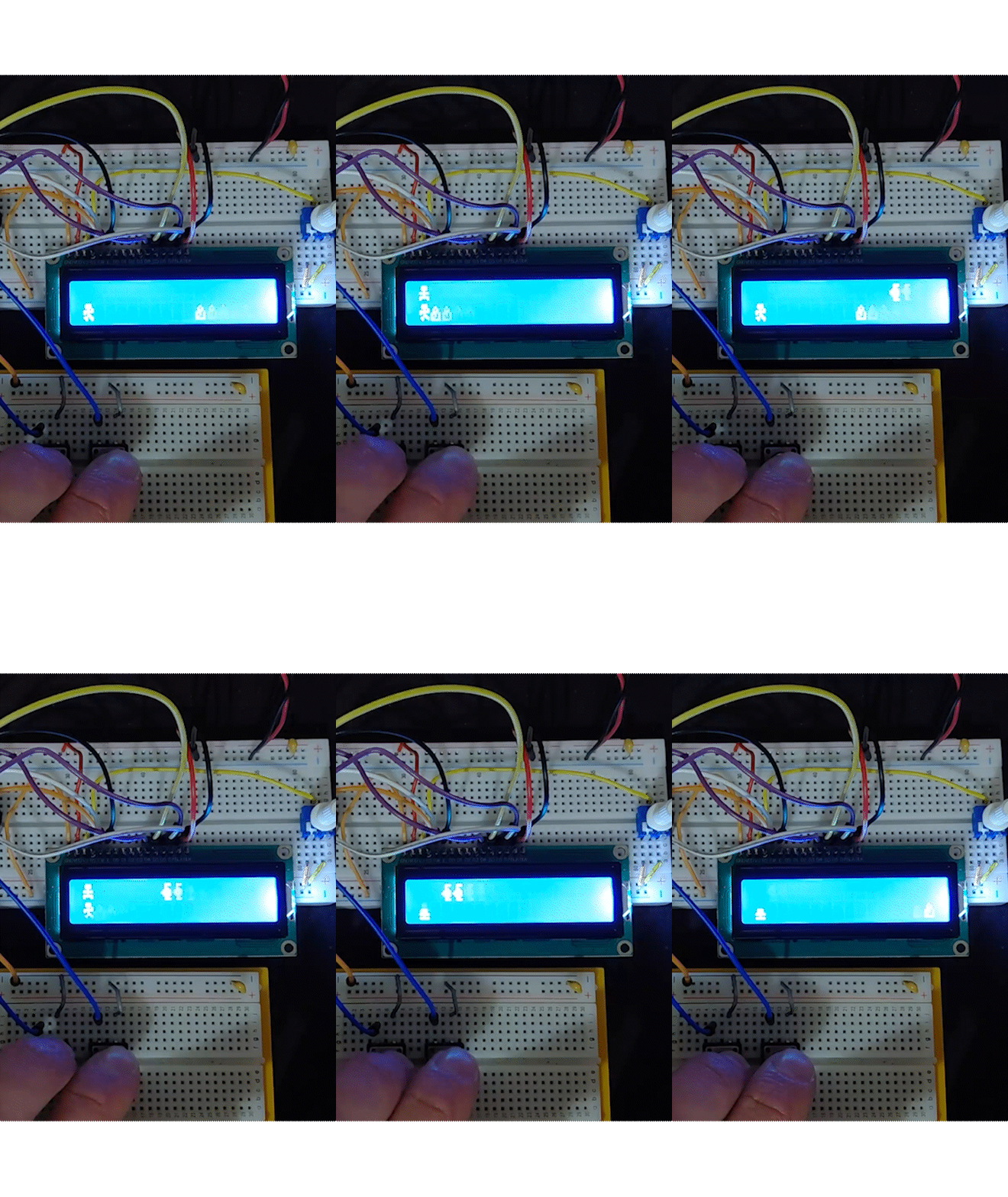
You control a man who is on the run. Avoid rocks and crows as you step closer towards freedom (or you’re maybe running away from the authorities, who knows). One button controls jumping, the other ducking. Whatever happens, make sure you don’t crash!
This is an side-scrolling endless runner game, eerily similar to Dino Run. Hmmmm. Each obstacle avoided increases your score by 1. Dodge rocks by jumping and crows by ducking.
Hardware Connections
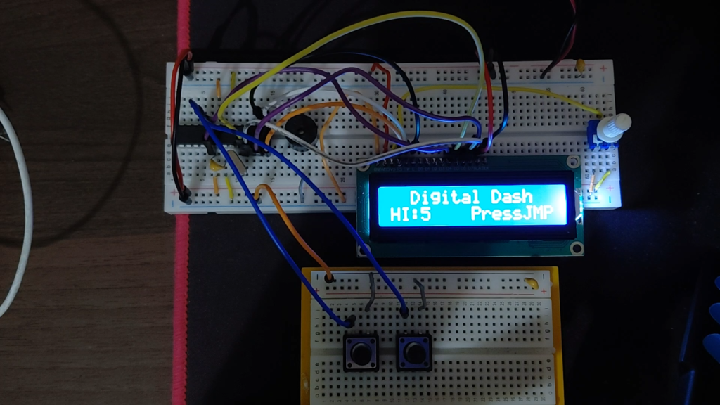
The schematic is available at my GitHub repository.
Highlights:
- LCD is connected in 4-bit mode
- Buzzer connects to an I/O.
- The two pushbuttons connect to an I/O with internal pullups enabled.
The Software
Each component (buzzer, pushbutton, lcd) gets a dedicated file. The .h file exposes the public API the rest of the code can use.
Full source code is located in my GitHub repository.
game.c/.h contains parameters to tune the game including: game speed, jump distance, duration of a jump, duck and the tones for jump, duck and death events. This is encapsulated in this file. However, what would be cool if this were adjustable in the main menu. I’ll record this as a feature for an extension of Digital Dash.
Project Structure
digital_dash/
├── Makefile                        # Build rules, fuse definitions, flash targets
├── README.md
├── digital_dash.elf                # Linked ELF (avr-gcc output)
├── digital_dash.hex                # Intel HEX for flash programming
├── digital_dash.map                # Linker map (symbol addresses, section sizes)
├── docs/
│   ├── CHANGELOG.md
│   ├── Theory.md
│   ├── digital_dash_amega328p_port_prompt.md
│   └── hardware_connections.md     # Pin table, ASCII schematic, BOM
├── src/
│   ├── main.c                      # Top-level state machine
│   ├── hardware_connections.h      # Pin definitions
│   ├── sys_tick.c / .h             # Timer0 CTC → 1 ms system tick + sys_millis()
│   ├── buttons.c / .h             # PCINT1 ISR debounce for jump (PC0) and duck (PC1)
│   ├── buzzer.c / .h              # Timer2 CTC + OC2A toggle → non-blocking piezo tones
│   ├── game.c / .h                # Core game logic: obstacles, collision, scoring
│   ├── sprites.c / .h            # PROGMEM glyph data → LCD CGRAM loader
│   ├── rng.c / .h                 # Seed engine + PRNG
│   └── high_score.c / .h         # Contains EEPROM code
└── build/                          # (empty — object files currently in src/)

../lcd_driver/                      # External shared library (sibling directory)
├── lcd_driver.c                    # HD44780 4-bit HAL: init, busy-flag polling, R/W
└── lcd_driver.h                    # GPIO macros, command opcodes, public API
Build System
MakeFile is used for building the project. Highlights:
- Target: Atmega328P
- CPU Frequency: 16MHz
- Programmer: USBasp
hardware_connections.h
Nothing to see here.
2 buttons are on PORTC, PC0/PCINT8 (Jump) and PC1/PCINT9 (Duck). Buzzer on PB3.
NOTE: Their serviced by the same PCINT_vect. This is possible since this ISR is shared among a group of I/O’s.
The LCD is configured for 4-bit mode on PD4 – PD7. However, these connections are absent from this file, rather their stored in lcd_driver.h. The Makefile imports this.
sys_tick.h/.c – The Game’s “Heartbeat”
Timer 0 is configured in CTC mode with an output compare match of 249. With a /64 clock prescalar, this generates an interrupt every 1ms.
sys_tick is the heartbeat of the game. Increasing it results in a lower game speed
The ISR increments s_ms. The API provides sys_millis() which returns the time elapsed. This is used to scroll the LCD and other stuff <Populate>.
The firmware never uses _delay_ms(). Since this is a busy wait, if we use it, it prevents other stuff such as LCD updating, game state changing and buzzer from getting serviced. The game momentarily FREEZES. By avoiding _delay_ms(), never block the firmware, thus ensuring each subsystem gets serviced. Since the firmware never uses it, this firmware implements the cooperative-scheduling pattern.
What is cooperative scheduling?
A cooperative scheduling pattern is a method to handle multiple tasks without requiring a RTOS. The idea is every task checks if there is work. If not, it relinquishes control to main(). Every task runs to completion before relinquishing control. This is called run-to-completion (RTC). NOTE: A task is completed by splitting it into mini-tasks which run many many times until task completion. This is the non-blocking aspect of cooperative-scheduling.
Alternatively, FreeRTOS uses pre-emptive scheduling. Where the scheduler rapidly switches between tasks, even if it has lapsed. Both methods convey the illusion of concurrency.
In the firmware, everything schedules against sys_millis().
Cooperative scheduling falls apart in two situations.
1. When two tasks must run simultaneously
2. A long un-interruptible task e.g. a cryptographic operation
A round-robin is the simplest cooperative structure. The tasks are called in order
buttons.h/.c
Buttons configured as input with internal pullups. Interrupts are enabled.
PCINT_vect is quite large. We determine what button was pressed, do stuff <populate> then call the tone associated with a jump or duck.
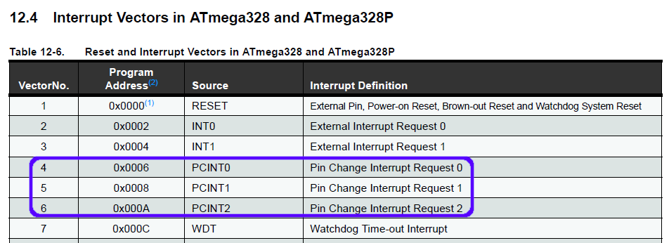
Up to 23 of the ATmega328p’s I/O’s can be configured as a Pin Change Interrupt (PCINTx).
If we interpret the excerpt from the datasheet, we learn that all 23 interrupt-compatible pins are grouped into 3 interrupt vectors. For the two buttons, they fall under PCINT1_vect. However, through some programming we are able to distinguish which button was pressed from the SAME ISR!
How do we know which button was pressed if an interrupt on a group of pins trigger the same ISR?
The ATmega328p has 3 PCMSKx registers, allowing you to enable which pins you want an interrupt for. This is mandatory since the pins are grouped together into 3 ISR’s (mentioned above). Part of initialization is selecting what bits we want.
I still haven’t answered the question. The hardware tells us Hey a pin from x group has called an interrupt. However, we don’t know which pin?
To determine which pin, we record the state of the pins then compare it with the new state. We then & it with either button. If this condition is true, then we’ve successfully determined the source of the ISR.
Afterwards, the ISR compensates for debouncing, updates the relevant variable that tracks if user is jumping (g_jump_edge) or ducking (g_ducking) then play the SFX via the buzzer. Before it finishes, the previous state is updated with the current state, preparing the hardware for a pin-change interrupt in the future.
buzzer.h/.c
Timer 2 is configured to generate certain tones. It’s transmits a PWM signal on PB3 in the audible hearing range.
The buzzer chimes according to certain gameplay events such as jumping, ducking and achieving death. This makes for a more interactive and engaging experience.
buzzer_tone_nb() plays a tone at a specific frequency for a specified duration by manipulating OCR2A.
sprites.h/.c
The custom glyphs are stored in flash, PROGMEM.
The .c file contains a 5×8 2D array of each sprite. These dimensions originate from the LCD specs. Each LCD cell is composed of a 2D array of 5 by 8 dots.
We reference each glyph via an array of pointers to uint8_t, k_glyph_table.
The 7 glyphs are loaded into CGRAM slots 0 – 6. To display a glyph, we pass in the CGRAM slot as a argument into Lcd_WriteChar(). By writing character codes 0 – 7 to the LCD’s DDRAM, we display our custom glyphs.
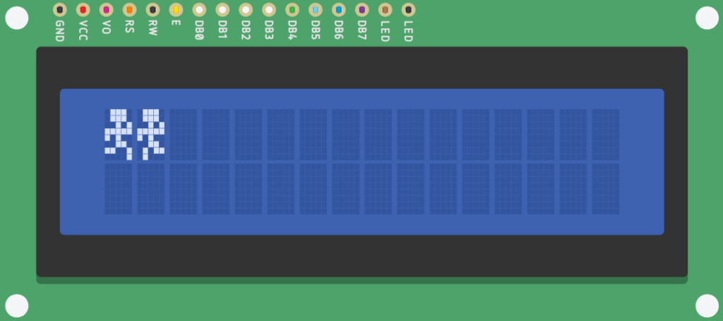
Attached below are the two glyphs which define the character sprite. Below is how this is rendered on the LCD. In game.c/.h, we rapidly switching between the two glyphs every 2 game ticks, thereby creating an illusion of running.
```
static const uint8_t PROGMEM k_step1[8] = {
    0x0Eu, /* 01110 */
    0x0Eu, /* 01110 */
    0x05u, /* 00101 */
    0x1Fu, /* 11111 */
    0x14u, /* 10100 */
    0x06u, /* 00110 */
    0x19u, /* 11001 */
    0x01u, /* 00001 */
};

static const uint8_t PROGMEM k_step2[8] = {
    0x0Eu, /* 01110 */
    0x0Eu, /* 01110 */
    0x05u, /* 00101 */
    0x1Fu, /* 11111 */
    0x14u, /* 10100 */
    0x06u, /* 00110 */
    0x0Bu, /* 01011 */
    0x08u, /* 01000 */
}
```
rng.h/.c
This file is responsible for seeding the game, providing a new experience each time the game is played.
It’s used to alter where the crow and rock respawns, resulting in a unpredictable and engaging gameplay experience.
rng_u16() returns a random 16-bit value. The PRNG algorithm used is inspired by George Marsaglia’s work.. If you would like to limit the random number to a range, the API exposes rng_range().
uint16_t rng_range(uint16_t lo_inclusive, uint16_t hi_exclusive)
{
    return lo_inclusive + (rng_u16() % (uint16_t)(hi_exclusive - lo_inclusive));
}
rng_rang() uses % operator to constrain the PRNG. How?
Firstly, the modulo operator returns the remainder after division. E.g. 11 % 6 = 5. This is easy.
However, what if the left operand is smaller than the right operand. E.g. 11 % 645.
The result is simply the left operand, which is the remainder. This can be explained by the formula below.
If the right operand (the dividend) fits into the left operand (divisor), zero times then Dividend = Remainder. Thus, Remainder = Dividend = Left operand.
Dividend = (Divisor * Quotient) + Remainder
The quotient is how many times the dividend fits in the divisor.
In rng_range(), if the PRNG is < the difference of the arguments, the random number is the difference of the arguments + the lower end. Otherwise, dividend is > divisor and normally modulo operation takes place. In both instances, the PRNG is constrained.
high_score.h/.c
This file is responsible for saving and returning the high score, which is saved in EEPROM.
NOTE: It doesn’t contain the actual game logic of tracking the user’s score.
avr/eeprom.h provides two functions to store values in EEPROM. The first one is eeprom_write() which like you probably guessed, writes to EEPROM. The other is eeprom_update(). The later actually verifies if the data has changed before writing to EEPROM. This is a game-changer since it avoids unnecessary writes. This extends EEPROM lifespan, which is 100,000 for the ATmega328p.
By using EEMEM attribute for eeprom variables, it saves us the headache of tracking addresses in eeprom. We label the variable EEMEM then hand it to the eeprom and say Here’s a variable. Store it wherever you like.
static uint16_t EEMEM ee_high_score = 0u;
static uint8_t  EEMEM ee_magic      = 0u;
In high_score_save(), we check if the the user has actually beaten the high score saved in EEPROM. If not, we do not perform a write operation. Thus, extending EEPROM write endurance.
game.c/.h
This file implements the actual game logic.
- Contains various parameters to tune the game including game speed, jump distance, duration of a jump, duck and the tones for jump, duck and death events. What would be cool if this were adjustable in the main menu. I’ll record this as a feature for an extension of Digital Dash.
- Contains
game_twhich stores all game objects
typedef struct {
    uint8_t  jump_phase;   /* 0..(JUMP_LENGTH-1) = airborne; JUMP_LENGTH+1 = grounded */
    uint16_t game_tick;    /* total ticks since game start; drives crow animation      */
    int8_t   crow_x;       /* column of crow (can be > 15 = off-screen right)          */
    int8_t   hill_x;       /* column of hill                                           */
    bool     player_y;     /* false = row 1 (ground); true = row 0 (jumping)           */
    bool     crow_go;      /* half-speed crow flip-flop: crow moves only when true      */
    uint16_t score;        /* obstacles successfully cleared this session               */
} game_t;draw_player(). The player has 2 primary movements, jumping or ducking. These are represented as different sprites which is sent to the LCD to display if the corresponding button is sent. Otherwise, the function draws the running animation by alternating between two sprites every 2 game ticks.
This function also implements the collision detection. The player’s position on the LCD is always column 0. The obstacles are actually moving towards the player (in software) rather than the player advancing towards the obstacles. Sorry for deceiving you. Thus, to implement collision detection we check if an obstacle is <1. For a crow, we check if player has ducked. If not, GAME OVER. For a rock, we check if player has jumped. If not, GAME OVER.
game_end() plays the death SFX and saves high score to EEPROM.
game_tick_update() updates the player’s position, draws the players, draws the obstacles, implements scoring and advances the game by one tick.
The two obstacles, the crow and hill scroll across the LCD at two different speeds (180ms and 90ms). This adds to the liveliness of the game, ensuring it’s not stale.
Row 0 is actually the top row. This is where crows are drawn. Row 1 is the bottom row.
main.c
Firstly, all the peripherals are initialized, then a super state machine is commenced via for (;;).
The firmware uses utility functions from the standard library
1. itoa() converts an integer into a string and stores it in a buffer. itoa(int value, char *str, int base).
2. size_t strlen(const char *s) counts how many characters in a string, excluding '\0'. It doesn’t convert a string into an int.
Other utility functions include:
1. dtostrf()
2. memset(), memcpy(). From <string.h>
3. bit_is_set(sfr, bit), bit_is_clear(sfr, bit). From <avr/sfr_defs.h>
4. wdt_enabl(), wdt_reset(), wdt_disable(). From <avr/wdt.h>
The implementation of the FSM is super simple. The states are stored in a struct and they are processed in an infinite loop (
for (;;)) due to a switch/case block.
// The 3 game states (Very simple)
typedef enum {
    STATE_SPLASH,
    STATE_PLAYING,
    STATE_GAMEOVER,
} state_t;
The game over screen flashes Jump to Continue every half a second, thereby inviting the player to play again.
STATE_SPLASH
Prints the opening menu to the LCD using the driver API. The program waits for a button press to transition to STATE_PLAYING.
STATE_PLAYING
We check either 90ms has elapsed. If yes, execute one frame of game logic. This updates the character position, draws the sprite, scrolls the LCD to the left and checks for collisions. If the player collides, a variable is set true which triggers a transition to STATE_GAMEOVER.
STATE_GAMEOVER
The score and high score are displayed on row 0, and “Jump to Continue” blinks on row 1 with a 500 ms cadence.
Showcase
FAQ
These are questions my brain raised. Treat it as a FAQ.
Describe the death sound that plays
Placeholder
This program is a side-scrolling endless runner. Describe the RNG of the program? How are the obstacles generated? Are they stored in an array?
Placeholder
What’s the difference between TICKSPEED and s_ms. Both are related to game-timing
Placeholder
I don’t understand what occurs in PCINT_vect.
We determine what pin raised an ISR by doing an & and mask operation.
If it’s a jump, we compensate for debouncing, set g_jump_edge and play the jump SFX.
Same story for a duck except we play the duck SFX.
How does the same ISR, PCINT_vect service 2 I/O’s?
Placeholder
loop_breaker tracks whether we’ve hit a collision. However, what I don’t understand is how does it cause a game over event. game_end() begins with executing the death sound.
Placeholder
How complex is the scoring system? Does the score increase as game time increases? Do certain obstacles award more score?
Placeholder
How is the high score tracked?
Placeholder
A floating ADC pin is used for RNG engine. Can Mersenne Twister be used. How much memory does the library occupy? I’m actually curious.
Placeholder