Background
A keypad is basically a number of pushbuttons. Their commonly found in security systems, calculators and the like. They’ve been digitally emulated for use in phones. For example a phone number is entered by pressing on a keypad. The lock screen is a variant of a keypad.

A keypad is great where we need multiple pushbuttons to record user input.
In this page, I’ll demonstrate the use of a 4×4 keypad. This components allows us to register 16 unique inputs. Basically, it’s 16 pushbuttons in one integrated component.
How does a keypad work?
Since a keypad is 16 pushbuttons in one package, let’s begin our discussion by examining how a pushbutton works. A pushbutton is a SPST switch. This means it has two terminals. One is connected to an MCU I/O, the other to ground. Pressing the button connects the I/O to ground. By configuring the I/O as a digital input, we can detect button presses. The I/O also enables its internal pullup resistor. This ensures we are always reading a known voltage state. We can then use this information to perform useful work in our code. Also, when working with buttons, you must consider debouncing. I’ll omit this for you to research.
A keypad is 16 pushbuttons however it is wired as a 2D matrix of rows and columns. Given a 4×4 2D matrix, we can have 16 unique keys. We connect each one to an MCU I/O.
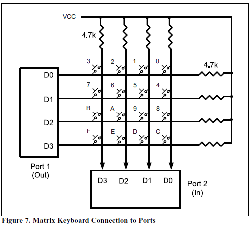
All the keys are pulled HIGH to VCC. The rows are connected to a port configured as OUTPUT’s whilst the columns are connected to a port configured as INPUT’s.
Pressing a key grounds it (i.e. shorts it). I.e. the keypad is active-low. We detect this using Port 2 (IN). In software, we continuously scan for a keypress.
When the Port is configured as an INPUT, we can sense the voltage on that pin.
Grounding rows and reading columns
We ground the rows one by one then read the voltage on the column. If a column is 0, it means that key is pressed. NOTE: Pushbuttons are active-low. We have detected a button press on a column however it could belong it one of four pushbuttons. The next task is to identify which row it belongs to.
NOTE: We ground the rows and read the columns. We can also do the opposite. Ground the columns, read the rows.
If D3-D0 = 1110 for rows and D3-D0 = 1011 for columns, that means that key [3][2] was pressed. This matches to key 2.
We can map each index to a keypress.
We ground the OUT port when determining what row the key belongs to.
MM74C923 bundles keypad scanning and decoding into one IC, freeing up the CPU and freeing I/O’s.
Project 1 – Hello World
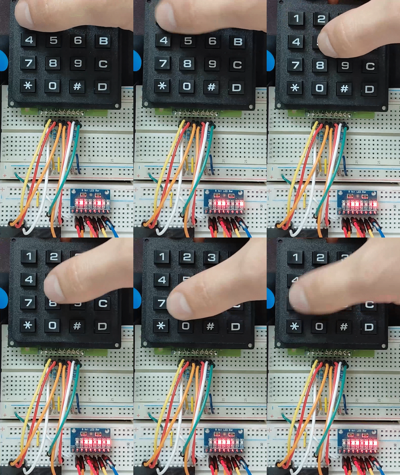
For this project, we’ll display the binary-equivalent of the ASCII character pressed on 8 LEDs. For example, key 3 will illuminate 4 LEDs, key 1 will illuminate 3. See the table below.
| Key | ASCII (Hex) | ASCII (Binary) | Expected LEDs ON (PD#) | Mapping |
|---|---|---|---|---|
| 1 | 0x31 | 0011 0001 | PD5, PD4, PD0 | D6, D5, D1 |
| 2 | 0x32 | 0011 0010 | PD5, PD4, PD1 | D6, D5, D2 |
| 3 | 0x33 | 0011 0011 | PD5, PD4, PD1, PD0 | D6, D5, D2, D1 |
| A | 0x41 | 0100 0001 | PD6, PD0 | D1, D7 |
Hardware Connections
We connect 4 I/O’s to the 4 rows and another 4 I/O’s to the columns. The keypad is then implemented using 16 SPST tactile pushbuttons. It may look confusing at first but I invite you to scrutinize it. I have wired it up as cleanly as possible without using a dedicated schematic symbol. Each row and column has a 4.7kΩ pull-up resistor.
8 LEDs are connected to PORTD. I found this LED module on AliExpress and thought Huh! That is useful. This saves me having to perform connections for 8 LEDs with current-limiting resistors back to ground. If you don’t have this, it’s fine. The schematic is still valid.
Since a 8×8 keypad schematic symbol is not available in vanilla KiCAD, I created an adhoc one using pushbuttons. If I am to use this in the future, it would save time to create a keypad symbol.
For further information, the schematic is available at my GitHub repository.
The Software
A dedicated/standalone keypad driver wasn’t created. Although, this is a good idea to promote code reusability.
Full source code is located in my GitHub repository.
Showcase
Project 2 – Print to UART
Let’s change gears and print the key to a serial terminal via UART, thereby validating the keypresses and our code.
Hardware Connections
The schematic is available at my GitHub repository. It’s equivalent to Project 1 minus the LEDs.
The Software
Full source code is located in my GitHub repository.
The Showcase
What we we learnt?
In conclusion, this page analysed the use of a keypad in isolation. We are now ready to integrate it into future projects as an adequate way of capturing user input.